

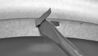
Bend Tabs Straight Up
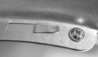
Flatten Tabs / Screw Secure
Tape Joints Along Flange
Assembly
Bend all the tabs straight up with a flat screwdriver.
Mate the two parts so that the screw holes line up.
Secure the flanges with five sheet metal screws.
Bend tabs down and tape the joints along the flange.
Installation
 Click Here for Printable Instruction Sheet
Installation
- Model LT90 should be measured as 1-1/2 feet against the total allowable duct length. See engineering information based on ASHRAE calculations and code references: 2012 IMC Table 504.6.4.1 and IRC Table M1502.4.4.1 for 10" radius fittings.
- Arrow indicates airflow direction from dryer and provides for proper male and female connections.
- When used with the Model 4D “Down” Dryerbox®, cut and insert a 3” long section of snaplock pipe to transition into port for adequate flex connection.